I. Classification of machining centres
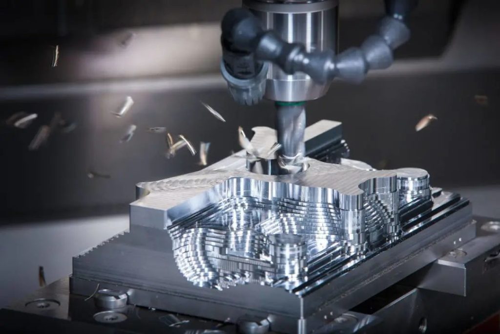
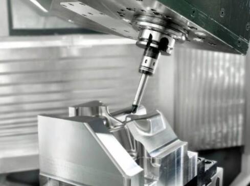
Machining centres are often divided into vertical machining centres, horizontal machining centres, gantry machining centres and universal machining centres according to the state of the spindle in space. Machining centres with the spindle in space in a vertical state are called vertical machining centres, and those with the spindle in space in a horizontal state are called horizontal machining centres.
Vertical machining centres
The structure is mostly of the fixed column type with a rectangular table, suitable for machining disc, sleeve and plate parts. Vertical machining centres usually have three linear motion coordinates, XYZ axis, and a fourth axis, A axis, can be installed on the table.
Vertical machining centres are easy to set up, easy to operate, easy to observe the machining situation, easy to debug the program, but affected by the height of the column and the tool change mechanism, can not machine too high parts. Vertical machining centres are simple in structure, have a small footprint and are less expensive.
Horizontal machining centres
Usually a mobile column is used, with the spindle box between the two columns, moving up and down along the guide rails. Horizontal machining centres usually have three linear motion coordinates, facing the machine, moving left and right for the X-axis, back and forth for the Z-axis and up and down for the Y-axis. Horizontal machining centres can also have a fourth axis, the A-axis, on the table. It is possible to machine parts such as spiral wire types and cylindrical cams.
The horizontal machining centre is not easy to observe when debugging the program and test cutting pins, inconvenient to monitor when machining, inconvenient to clamp and measure parts, but easy to line up pins when machining. Compared with the vertical machining centre horizontal machining centre structure is complex, covers an area of large, the price is higher than suing.
Double column machining centres
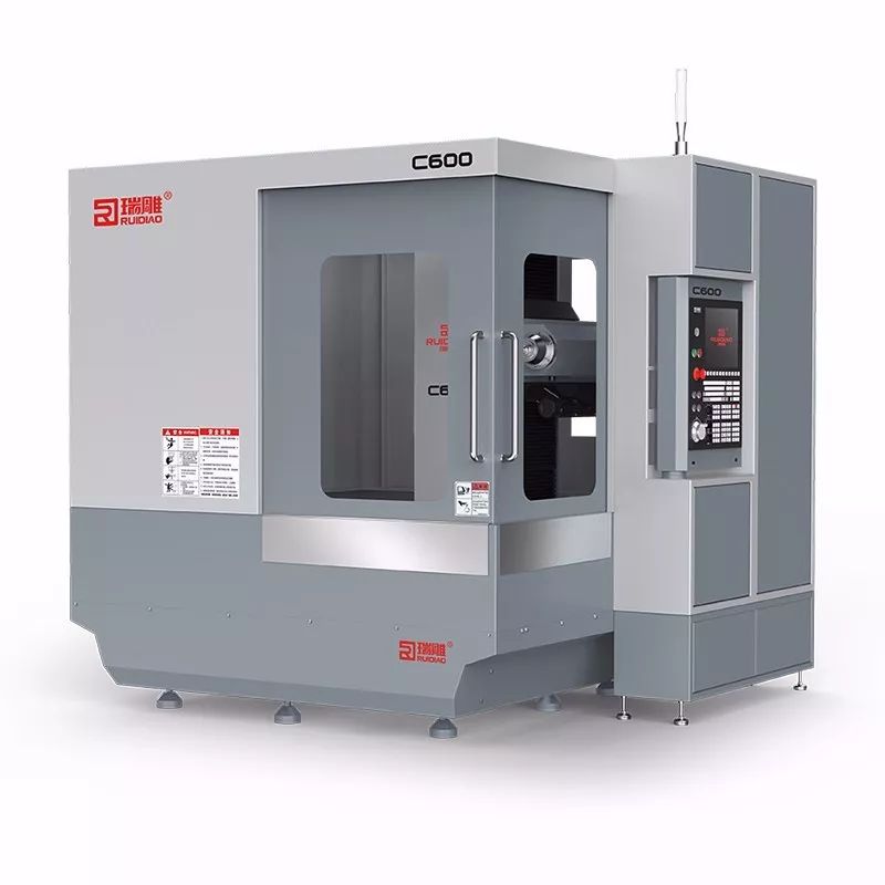
Most of its spindles are set vertically, with ATC systems and interchangeable spindle head attachments. The system software is more versatile and can be used for multiple purposes, making it suitable for machining large parts.
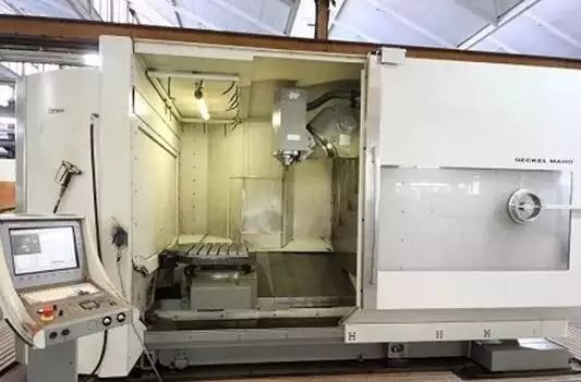
Universal machining centres
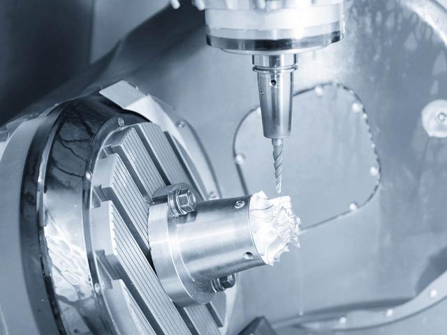
The universal machining centre is a five-sided machining centre with the functions of a vertical machining centre and a horizontal machining centre. The workpiece can be machined on all sides and top surfaces except for the mounting surface after one clamping. Common universal machining centres are: 1) The spindle can be rotated by 90°, working both like a vertical machining centre and a horizontal machining centre. 2) The spindle does not change direction and the table rotates by 90° with the workpiece. The machining of five surfaces is completed.
According to the number of tables and functions: there are single table machining centre, double table machining centre, and multi-table machining centre.
II. the structure of the machining centre composition
From a general point of view, it is mainly composed of the following major parts.
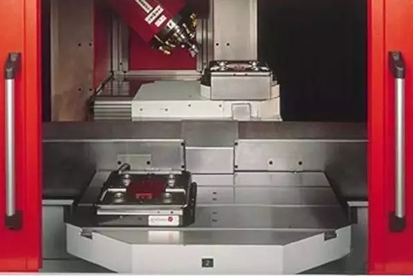
1、Foundation components
It is the basic structure of the machining centre, consisting of the bed, column and table, etc. They mainly bear the static load of the machining centre and the cutting load generated during machining, and therefore must be sufficiently rigid. These large parts can be cast iron parts or welded steel parts, they are the largest volume and weight of the machining centre.
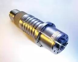
2、Spindle parts
By the spindle box, spindle motor, spindle and spindle bearings and other parts of the composition. The spindle starts, stops and changes speed and other actions are controlled by the numerical control system, and through the tool mounted on the spindle to participate in the cutting movement, is the power output components of the cutting process. It is a key component of the machining centre and determines the machining accuracy and stability of the machining centre.
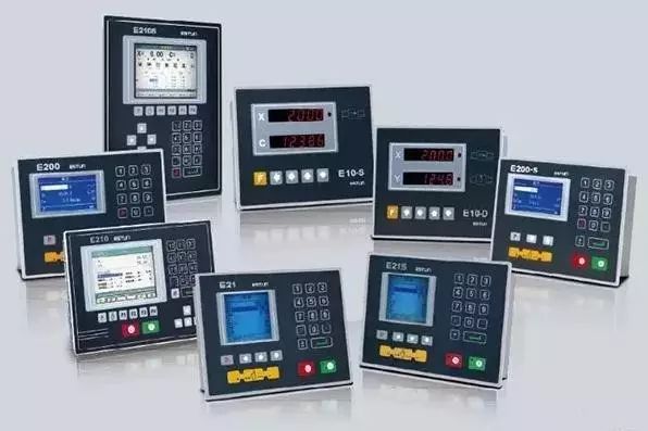
3、CNC system
The CNC part of the machining centre is made up of the cNc device, the programmable controller PLC, the servo drive and the operating panel.
4、Automatic tool changing system
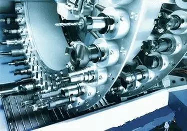
It consists of tool magazine, manipulator, drive mechanism and other components. When the tool needs to be changed, the CNC system issues a command and the robot (or by other means) takes out the tool from the tool magazine and loads it into the spindle hole. It solves the task of automatic storage, selection, handling and exchange of tools between processes in the continuous machining of multiple processes after a single clamping of the workpiece.
The tool magazine (tool tray) is a device for storing all the tools used in the machining process. Tool magazines are available in disk and chain types, with capacities ranging from a few to several hundred tools. The structure of the tool arm is also different according to the relative position and structure of the tool magazine and spindle, such as: single arm type, double arm type, etc. Some machining centres do not use the tool arm but use the spindle box or the movement of the tool magazine directly to achieve tool change.
5、Auxiliary devices
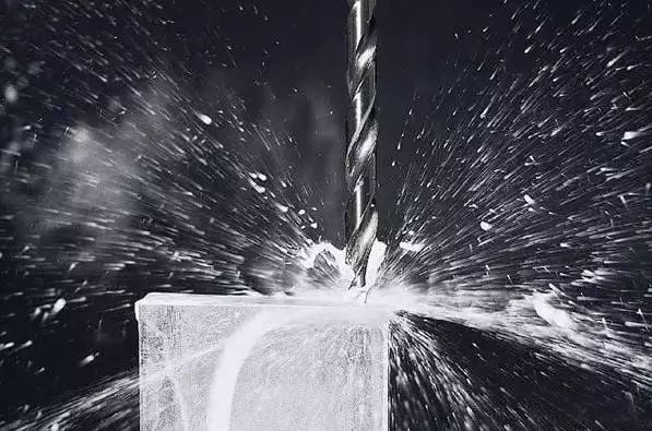
Including lubrication, cooling, chip removal, protection, hydraulic, pneumatic and detection systems and other parts. Although these devices are not directly involved in the cutting movement, they play a role in guaranteeing the machining efficiency, accuracy and reliability of the machining centre, and are therefore part of the machining centre.
6、APC automatic pallet exchange system
Some machining centres in order to achieve into a part of the unmanned or further shorten the non-processing time, the use of multiple automatic exchange table way reserve workpiece, a workpiece installed in the table for processing at the same time, another or several tables can also load and unload other parts, when the completion of a table parts of the processing, then automatically exchange the table, the processing of new parts, which can reduce auxiliary time and improve processing efficiency.
III. the main processing objects of the machining centre
1、the box class parts
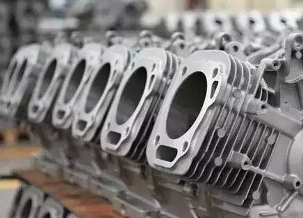
Box-type parts generally refers to more than one hole system, the internal cavity, in the length, width and height of the direction of a certain proportion of the parts.
2、Complex surfaces
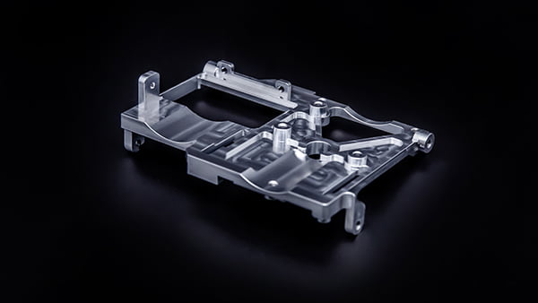
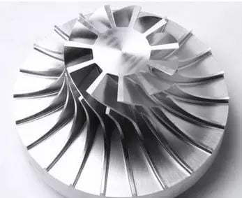
Complex surfaces are difficult, if not impossible, to machine using normal machining methods.
3、Shaped parts
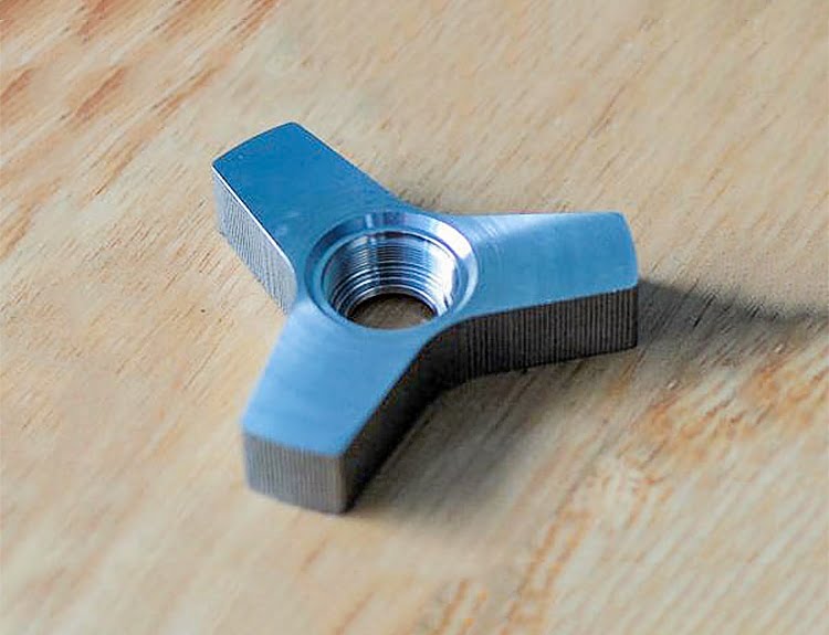
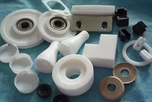
Shaped parts are irregularly shaped parts, mostly requiring point, line, surface multi-station hybrid processing. Such as forks.
4、disc, sleeve, plate parts
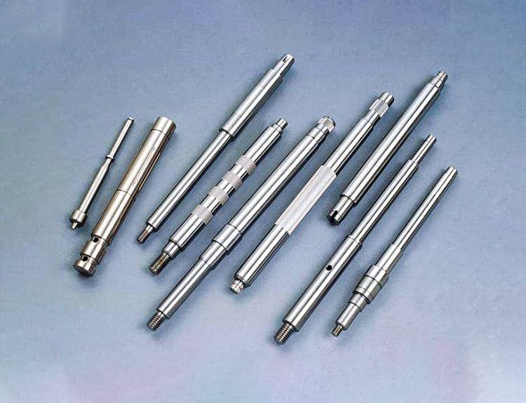
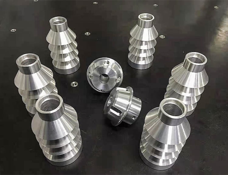
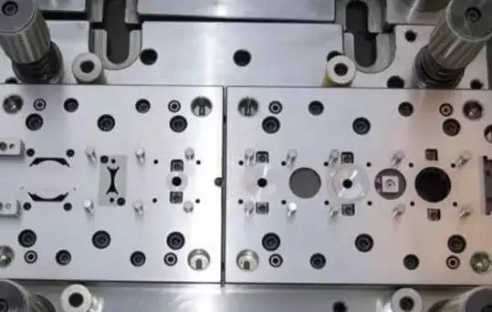
With a keyway or radial hole or end face has a distribution of the hole system, curved disk sleeve or shaft parts, such as a flange with the sleeve, with a keyway or square head shaft parts, etc., and has more hole processing plate parts, such as a variety of motor cover, etc.. End face has a distribution of hole system, curved disc parts should choose vertical machining centre, with radial holes optional horizontal machining centre.
5、periodic production of parts
Machining centre with parts, the time required mainly includes the basic time and preparation time, of which, the preparation time accounts for a large proportion, such as: process preparation, programming, parts first test cut, etc., these times are very long, the use of machining centre can store the contents of these times for later repeated use. In this way, these times can be saved when the part is processed later. The production cycle time can then be significantly reduced.

