1.Preparation for start-up
Machine tools in each start-up or machine by emergency stop reset, the first back to the machine reference zero position (i.e. back to zero), so that the machine has a reference position for its subsequent operations.
2.Clamping workpieces
Before clamping the workpiece, the surfaces should be cleaned and not sticky with oil, iron filings and dust, and the burrs on the surface of the workpiece should be removed with a file (or oil stone).
The clamping iron must be smoothed by the grinding machine to make the surfaces smooth and flat. Code iron, nut must be strong, can reliably clamp the workpiece, some difficult to clamp small workpiece can be directly clamped on the tiger; machine table should be clean, no iron chips, dust, oil; pad iron is generally placed on the four corners of the workpiece, the span of the workpiece must be too large in the middle of the additional high pad iron.
According to the size of the drawing, use the ruler to check whether the workpiece's length, width and height are qualified.
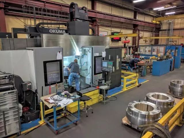
When clamping the workpiece, according to the programming instructions, the clamping arrangement should be considered to avoid machining parts and the possibility of the tool head touching the fixture during machining.
After the workpiece has been placed on the pads, the workpiece datum surface should be pulled according to the drawing and the workpiece should be checked for perpendicularity if it has been ground on all six sides.
The workpiece must be tightened after pulling the table to prevent the workpiece from being shifted in the process due to poor clamping; pull the table again to make sure that the clamping error does not exceed the difference.
3.Number of workpiece touches
Clamped workpiece can be used to touch the number of head to determine the processing reference zero, touch the number of head available photoelectric and mechanical two.
The photoelectric type is stationary, the mechanical type turns 450~600rpm. fractional touch count manually move the table X axis, make the touch count head touch a side of the workpiece, when the touch count head just touches the workpiece so that the red light is on, set the relative coordinate value of this point as zero; then manually move the table X axis to make the touch count head touch another side of the workpiece, when the touch count head just touches the workpiece, write down the relative coordinate at this time.
Subtract the diameter of the head (i.e. the length of the workpiece) from the relative value and check that the length of the workpiece meets the drawing requirements.
Divide this relative coordinate number by 2 and the resulting value is the middle value of the X-axis of the workpiece, then move the table to the middle value on the X-axis and set the relative coordinate value of the X-axis at this point to zero, which is the zero position on the X-axis of the workpiece.
Carefully record the mechanical co-ordinate value of the zero position on the X-axis of the workpiece in one of G54 to G59 and let the machine determine the zero position on the X-axis of the workpiece. Once again, check the data carefully for correctness. The procedure for setting the zero position on the Y-axis of the workpiece is the same as for the X-axis.
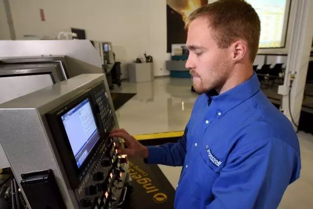
4.Workpiece CAM software programming
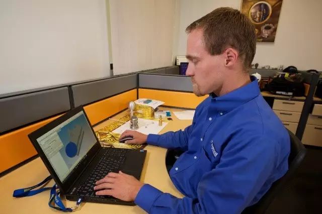
The programmer selects the workpiece to be machined, programs it with the CAM software WorkNC, generates the toolpath, performs an interference check on the toolpath with the WorkNC simulation simulation module and post-processes it after the interference check to generate a safe and stable NC code for transmission to the shop floor on the machine.
5.Prepare all tools according to the programming work instructions
Change the tool to be machined according to the tool data in the programming instructions, let the tool touch the height gauge on the datum and set the relative coordinate value of this point to zero when the red light of the gauge is on. Move the tool to a safe place and manually move the tool downwards by 50mm, setting the relative coordinate value of this point to zero again, which is the zero position of the Z-axis.
Record the mechanical coordinates of this point in one of G54 to G59. This completes the zero setting for the X, Y and Z axes of the workpiece. Once again, check the data carefully for correctness.
The single-sided touch count also touches one side of the X and Y axes of the workpiece in the same way as above, and the radius of the X and Y axes of this point is the zero position of the X and Y axes by offsetting the radius of the touch count head, and finally the mechanical coordinates of the X and Y axes are recorded in one of G54 to G59. Once again, check the correctness of the data carefully.
To check the correctness of the zero point, move the X and Y axes to the side overhang of the workpiece and visually check the correctness of its zero point according to the dimensions of the workpiece.
Copy the program file to the computer according to the file path in the programming work instructions.
6.Setting of processing parameters
Setting of spindle speed in machining: N=1000×V/(3.14×D)
N: spindle speed (rpm/min)
V: cutting speed (m/min)
D: tool diameter (mm)
Feed rate setting for machining: F=N×M×Fn
F: feed rate (mm/min)
M: number of cutting edges of the tool
Fn: cutting volume of the tool (mm/rev)
Cutting volume per edge setting: Fn=Z×Fz
Z: number of cutting edges of the tool
Fz: cutting volume per edge of the tool (mm/rev)
7.Start-up processing
At the beginning of the execution of each program must carefully check whether the tool used is the one specified in the programming instructions. When you start machining, set the feed speed to the minimum, single section execution, fast positioning, tool drop, tool feed must be concentrated, the hand should be placed on the stop button to stop immediately if there is a problem, pay attention to observe the direction of tool movement to ensure the safety of tool feed, and then slowly increase the feed speed to the appropriate, at the same time to the tool and workpiece plus coolant or cold air.
Do not move too far from the control panel when roughing, and stop in time to check any abnormalities.
After roughing, pull the table once more to make sure the workpiece is not loose. If there is, it must be recalibrated and the number touched.
Optimise the machining parameters during the machining process to achieve the best possible results.
As this process is a key process, after the workpiece is machined, the main dimensional values should be measured for consistency with the drawing requirements, and if there is any problem, the shift leader or programmer should be informed immediately to check and solve the problem.
Type of machining: hole machining: before drilling on the machining centre must be positioned with a centre drill, then drill with a drill bit 0.5~2mm smaller than the drawing size, and finally finish with a suitable drill bit.
Reaming: the workpiece should also be reamed with the centre drill first, then drilled with a drill 0.5~0.3mm smaller than the drawing size, and finally reamed with a reamer, and the spindle speed should be controlled within 70~180rpm/min.
Boring: Boring of the workpiece should be done with a centre drill for positioning, then with a drill smaller than the drawing size by 1~2mm, then with a rough boring tool (or milling tool) until only a single side of about 0.3mm is left, and finally with a fine boring tool with a pre-adjusted size for fine boring, the last fine boring margin should not be less than 0.1mm.
Direct Numerical Control (DNC) operation: Before DNC machining, you have to clamp the workpiece, set the zero position and set the parameters. Open the machining program to be transferred in the computer for checking, then let the computer enter the DNC state and enter the file name of the correct machining program. On the machining machine press the TAPE key and the program start key, at which point the machine controller appears with the flashing word LSK. Pressing the ENTER keypad on the computer then allows the DNC transfer to be processed.
8.Content and scope of worker self-inspection
The processor must read the process card before processing, know clearly the part of the workpiece to be processed, its shape, the dimensions of the drawing and know the content of the next process.
The workpiece should be measured before clamping to see if the dimensions of the blank are in accordance with the drawing, and the workpiece must be carefully checked when clamping to see if it is placed in accordance with the programmed work instructions.
Self-checking should be carried out in time after the rough machining is completed, so that any data with errors can be adjusted in time. Self-checking content is mainly for the location of the processing parts size. For example: whether the workpiece is loose; whether the workpiece is correctly centred; whether the size of the machining part to the reference edge (reference point) is in accordance with the drawing requirements; the position size of the machining parts in relation to each other. After checking the position dimensions, the roughing shape should be measured (except for circular arcs).
After rough machining self-check before finishing. After finishing, the worker should carry out a self-check of the shape and dimensions of the machined parts: for vertical machined parts, check the basic length and width dimensions; for bevelled machined parts, measure the dimensions of the base points marked on the drawing.
The worker should complete the self-inspection of the workpiece and confirm that it conforms to the drawing and process requirements before removing the workpiece and sending it to the inspector for special inspection.

