Mechanical parts process structure
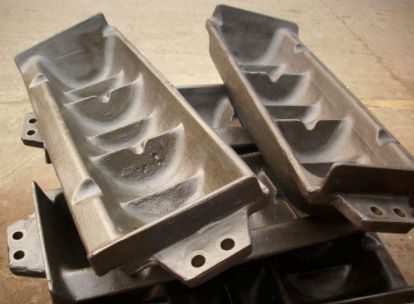
First of all, the structure of mechanical parts should adapt to the production conditions, batch size, mass production and large production equipment conditions, and die forging blanks should be used; The parts with complex shapes and sizes shall be cast blanks.
When producing parts in single piece or small batch, casting or die forging blanks should be avoided, otherwise the utilization rate of dies will be too low and the cost will increase. Welding blanks or free forging blanks should be used. Due to the different methods of obtaining the blank, the structure of the part should also be different.
How do we choose materials when designing castings? The minimum wall thickness of the casting shall meet the requirements of liquid metal fluidity.
The wall thickness of each part of the casting shall be uniform and not too thick to avoid shrinkage cavity defects. The casting joints with different wall thicknesses shall adopt a uniform transition structure, and there shall be appropriate casting rounding at each joint. The parting surface shall be reasonably selected. The workbench perpendicular to the parting surface shall have an appropriate casting slope, so as to facilitate molding and start-up of the mold and avoid dead corners that cause molding difficulties, Avoid using live blocks. The structure of castings shall also be easy to remove sand.
When designing forgings and stamping parts, the shape of the parts shall be simple and shall not be too deep for manufacturing. For die forging parts, appropriate forging slope and corner radius shall be reserved, and symmetrical shape shall be designed as far as possible. For free forging parts, taper and wedge shape shall be avoided, and reinforcement and lug on the base are not allowed. During the design of welding parts, it is necessary to use as few bevels as possible to avoid the welds with concentrated design stress. The welds shall be staggered to reduce the stress and minimize the stress on the welds.
Avoid sharp corners and corners. Corners are the places where quenching stress is most concentrated and often become the starting point of quenching cracks. Therefore, when designing parts with sharp corners and edges, rounded corners and chamfers should be used as much as possible, and the radius of the corners should be larger.
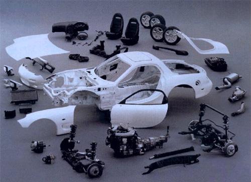
Avoid thick and thin parts, which are easy to deform and crack due to uneven cooling during quenching and cooling. For this reason, the process can solve the problem of structural thickness difference of parts by opening holes, thickening the parts too thin and reasonably arranging the hole positions.
The shape of the parts should be simple, closed and symmetrical. The shape of the parts should be open or asymmetric. During heat treatment, the stress distribution is uneven, so it is easy to cause deformation.
Combined structure, especially complex shape, or different parts have different performance requirements,To improve the structural rigidity of parts, the structure of parts shall ensure the possibility, convenience and accuracy of processing, and the design of part structure shall ensure that it can not only be processed, but also be easily processed to meet the accuracy requirements of parts.
The structure of the parts shall ensure the possibility and convenience of assembly and disassembly, that is, the design of the part structure shall ensure that it can not only be assembled and disassembled.

