The machining flatness tolerance is the condition that the actual shape of the plane element on the part keeps the ideal plane, that is, the flatness degree of the plane element commonly referred to. The flatness tolerance is the maximum allowable variation of the actual surface from the ideal plane. There are many plane elements on the parts, such as flat plate, workbench surface, end face of parts, box joint surface, etc. All kinds of plane elements on the parts, regardless of their location, shape profile changes, the geometric characteristics are exactly the same.
Therefore, the flatness tolerance zone has only one form, that is, the spacing equals the tolerance value. The region bounded by two parallel planes. But in the production, according to the functional requirements and structural characteristics of the parts, the flatness requirements appear in a variety of different forms:
(1) flatness tolerance requirements for the whole cable under test. It refers to the requirements for the whole range of elements of the plane under test, and the tolerance zone is the area bounded by two parallel planes within the whole range of elements under test, whose spacing is equal to the tolerance value t.
(2) Additional requirements within the local scope of the measured elements. It means that in addition to the flatness tolerance of the whole measured element, the drawing also gives any local range, and the further flatness tolerance requirement c is composed of two parts: the first is the area bounded by two parallel planes with spacing equal to the tolerance value t in the whole measured element range; The other is a region within the above tolerance zone bounded by any given local range with a spacing equal to two parallel flats of the local range tolerance value t1.
(3) Coplanar requirement refers to the requirement that several measured elements on the same plane control their flatness error variation with the same flatness tolerance zone. The tolerance zone is defined by two parallel planes with spacing equal to the tolerance value t within the range of all measured elements.
The common methods for machining flatness tolerance error of machining are as follows:

Flat crystal interferometry:
The working face of the optical flat crystal is used to reflect the ideal plane, and the flatness error value of the measured surface is determined directly by the bending degree of the interference fringe. Mainly used for measuring small planes.
Meter measurement method:
Meter measurement method is to put the measured parts and micrometer on the standard marble platform, with the standard marble plane as the datum of measurement, with micrometer along the actual surface point by point or along a few straight direction measurement.
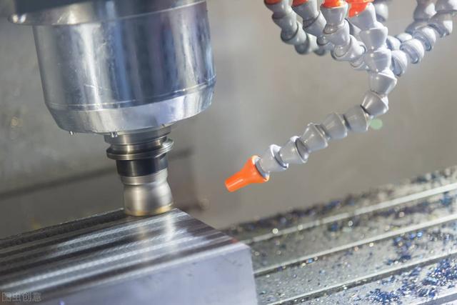
Meter measuring method assessment datum is divided into three point method and diagonal method, three point method is the ideal plane determined by the furthest three points on the actual surface measured as the assessment datum, measured first will be measured on the actual surface furthest three points adjusted to the height of the standard marble platform; In the diagonal method, the four corner points on the actual surface are first adjusted to equal height according to the diagonal line, and then measured with a micrometer. The large variation measured by the micrometer on the whole actual surface is the flatness error of the actual surface.
Liquid plane method:
The liquid plane method is to use the liquid plane as the datum of measurement, and the liquid plane is composed of the liquid level in the connected tank, and then the sensor is used to measure. This method is mainly used to measure the flatness error of a large plane.
Beam plane method:
In the beam plane method, a quasi-value telescope and a target lens are used for measurement, and the beam plane formed by the three farthest points on the actual surface is selected as the reference plane for the measurement of flatness error.


